Dependency matrices
For small systems, a simple “boxes and arrows” diagram is often sufficient to show the structure of dependencies between components.
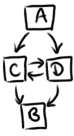
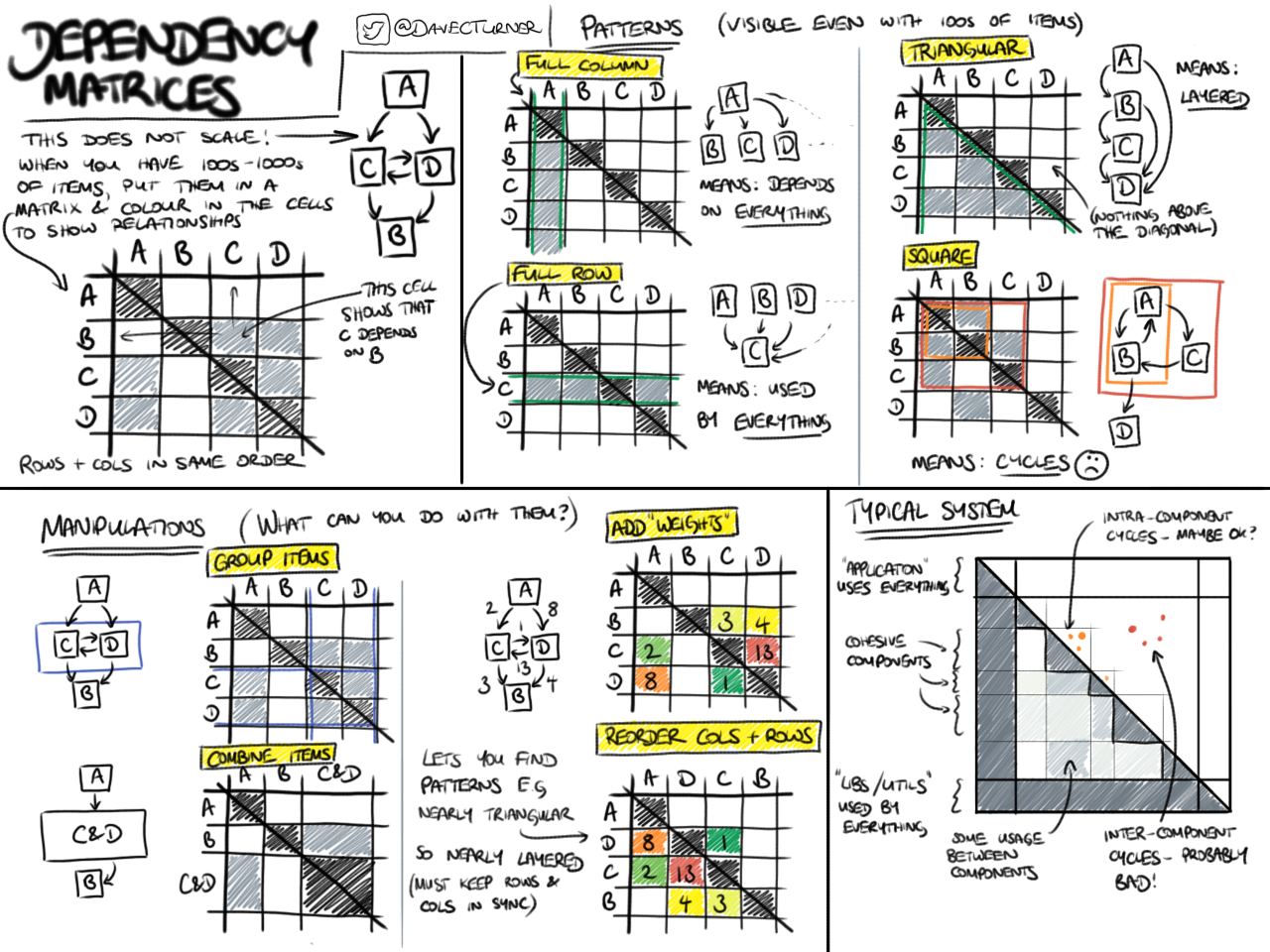
This does not scale. For larger systems, it is much better to draw a dependency matrix.
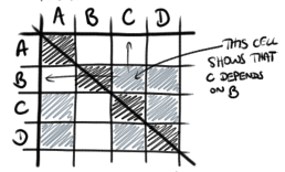
Each row and column represents a component (in the same order) and the cells are shaded to show the existence of relationships between them.
Patterns
A big advantage of this view is that certain kinds of dependency pattern can be identified by eye. Here are some examples.
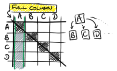
A full column indicates a component that depends on everything.
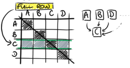
A full row indicates a component on which everything depends.
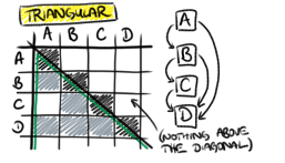
A triangular matrix indicates that the system is well-layered, with the order of the rows and columns indicating the order of the layers.
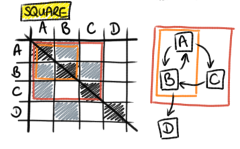
A filled-in square indicates a dependency cycle. More generally, filled-in cells above the diagonal indicate layering violations, which might arise due to dependency cycles.
Manipulations
There are some natural manipulations that you can do to navigate a dependency matrix.
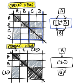
Sometimes it makes sense to group subcomponents together into larger components, either by highlighting the boundaries (e.g. the blue lines around the rows and columns for C and D) or even by combining them together.
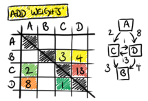
Sometimes you can add information about the strengths of the relationships between components by adding numbers and colours to the cells.
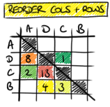
Sometimes the components need to be reordered to, e.g., fix layering violations. It is important that the orders of the rows and columns are kept synchronised. If the matrix cannot be made triangular by this kind of reordering then it contains dependency cycles.
A typical system
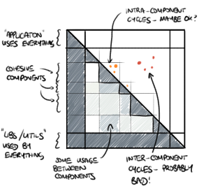
Typical systems often have dependency structures a little like this. At the top is an “application” layer which ties all the components together, and at the bottom is a layer of “utilities” or a “library” that is used by all the components. In between is a set of cohesive components with heavy intra-component dependencies but typically only light inter-component dependencies.
Sometimes it is necessary to have intra-component dependency cycles, but often inter-component dependency cycles indicate design problems.