Twinkly lights
A while back I got hold of a WS2811-based LED string and thought it’d be fun to play around with it with a microcontroller. The string is a sequence of bulbs (a.k.a. pixels) connected by three wires, where each bulb contains a red, green and blue LED as well as a WS2811: a little chip that lets you control the brightnesses of the three LEDs digitally. WS2811 is one of the controllers behind the Adafruit Neopixel series of individually-controllable LEDs, but you can also get cheaper WS2811-based LED strings from elsewhere.
These controllers use a serial protocol to set the colour of each pixel in the string in order. Each pixel’s colour is described by a block of 24 bits: 8 bits of red level, then 8 bits of green level and then 8 bits of blue level, each transmitted MSB-first. The first block of 24 bits sets the colour of the pixel nearest to the controller; the second sets the colour of the second pixel, and so on. The whole string acts as a big shift register: the first block of 24 bits is consumed by the first pixel, and then it passes all subsequent bits down the line; the second block of 24 bits sent by the controller is the first block passed to the second pixel, so it consumes this block and then passes all subsequent bits along, and so on. Each pixel carries on passing data along the line for as long as there is data to pass, but at the end of the frame the pixels all go back into the “consume the first 24 bits” mode, allowing you to send the next frame. Each pixel keeps displaying its last-received colour until it receives another one.
The three wires that connect the LEDs are +5V, GND and data, so there’s no clock line. To avoid the need for a separate clock line the protocol is entirely timing-based: each bit is transmitted as a 2.5µs-long frame comprising a period of +5V and then a period of 0V, where the +5V period is 0.5µs for a clear bit and 1.2µs for a set bit. There is also a “reset” pause of 50µs which puts each pixel back into the “consume the first 24 bits” mode.
The microcontroller I’m using is an ATmega328P (the controller used in Arduinos) with a 16MHz clock. Translating the timings into cycles, each bit is 40 cycles (2.5µs) which is either 8 cycles (0.5µs) high then 32 cycles (2.0µs) low for a clear bit, or else 19 cycles (1.2µs) high then 21 cycles (1.3µs) low for a set bit. The reset needs to take at least 800 cycles.
There’s an Arduino library called FastLED for talking to
WS2811 controllers, which basically works by putting all the colour values for
a frame into an array in RAM and then calling a show() function that streams
this array out as the necessary carefully-timed stream of pulses. The main
issue with the buffer-and-stream approach is that it uses a lot of RAM for the
buffer. The ATmega328P has 2kB of RAM, which is only enough for 85 24-bit
pixels (minus program overhead), and I’d also maybe like to work with an even
smaller device like the
ATtiny85 with just 512B
(up to 21 24-bit pixels).
On the other hand, 40 cycles per bit is absolutely loads when all it needs to
do is switch a data line high, wait for a bit, switch it low, and wait for a
bit more. FastLED’s show() function must spend most of its time just waiting.
If we could do some calculations in that waiting time then maybe we could
compute the colour that each pixel should be in a just-in-time fashion, i.e.
while transmitting the colour of the previous pixel. This might let us increase
the number of pixels in the string without a corresponding increase in the RAM
that’s needed, meaning we could support arbitrarily many pixels with a very
small controller.
There’s all sorts of effects that are possible to generate algorithmically like this, and I thought it’d be fun to do something with a bit of (pseudo-)randomness, so I settled on trying to make the lights twinkle as pleasingly as possible.
Timing constraints
The datasheet indicates that the timing of the pulses must be accurate within ±150ns (±2.4 cycles at 16MHz) but there is some evidence that in practice the constraints are not as strict as that. That said, I wanted to see how close I could get to the nominal timings for the sake of the exercise, so I really wanted to be able to count cycles accurately. The usual way to write code for this kind of microprocessor is to use something like C and compile it down to an image that runs on the chip, but this doesn’t give enough visibility about how many cycles everything takes, so I decided to drop down to writing raw AVR assembler and using the AVR Instruction Set Manual which gives details of the cycle counts of each instruction.
Anatomy of a twinkle
A really good twinkle is more than just switching the light on and then off
again. It looks much better if it starts out dim for a bit, then briefly
flashes brightly, and then goes back to being dim for a bit longer before going
out. It’s also important that the twinkles are not all synchronised. I ended up
settling on a 7-frame animation involving 3 colours that went DIM, DIM,
MEDIUM, BRIGHT, MEDIUM, DIM, DIM, and decided to read the actual
colours from a table so that I could customise them later on.
To trigger the animations randomly, I used a 7xn table of random bytes (where n is the number of pixels to drive):
               P I X E L
       0  1  2  3  4  5  6  7  8  9 ...
   0: dd f1 5a db ba 3d d5 7b 8e e1 ...
F  1: 57 82 4a 8c 60 b6 3f a1 b1 42 ...
R  2: f8 a1 cd 78 4f 85 e1 2b 2c 92 ...
A  3: c0 4b a3 54 52 df f1 f2 4e 09 ...
M  4: 6a a3 5a 5e 7d e4 45 5c 24 06 ...
E  5: f0 a4 61 34 b5 0b 15 14 dc fa ...
   6: 5b 94 cf 0e 15 10 cf aa 42 4b ...
I chose one particular byte, 0xba, as the trigger value, and used this to
decide on the state of each pixel. In the table here, pixel 4 has the trigger
value 0xba in the top row (corresponding to frame 0) which indicates that
pixel 4 is at frame 0 of the animation and should display the corresponding
colour. None of the other pixels have 0xba in their columns, so they are all
inactive and should display the background colour.
In the next frame the table moves down one row and a new random row is generated at the top:
               P I X E L
       0  1  2  3  4  5  6  7  8  9 ...
   0: c7 00 79 e6 f2 4f bd 6e 49 b7 ...  <- new row
F  1: dd f1 5a db ba 3d d5 7b 8e e1 ...  <- previously frame 0 row
R  2: 57 82 4a 8c 60 b6 3f a1 b1 42 ...  <- etc.
A  3: f8 a1 cd 78 4f 85 e1 2b 2c 92 ...
M  4: c0 4b a3 54 52 df f1 f2 4e 09 ...
E  5: 6a a3 5a 5e 7d e4 45 5c 24 06 ...
   6: f0 a4 61 34 b5 0b 15 14 dc fa ...
Since pixel 4 now has the trigger value 0xba in its frame 1 row, this
indicates that it should display the colour that corresponds with frame 1. This
continues:
               P I X E L
       0  1  2  3  4  5  6  7  8  9 ...
   0: 93 05 ba d7 83 1f 8a 9f 62 42 ...  <- new row
F  1: c7 00 79 e6 f2 4f bd 6e 49 b7 ...
R  2: dd f1 5a db ba 3d d5 7b 8e e1 ...
A  3: 57 82 4a 8c 60 b6 3f a1 b1 42 ...
M  4: f8 a1 cd 78 4f 85 e1 2b 2c 92 ...
E  5: c0 4b a3 54 52 df f1 f2 4e 09 ...
   6: 6a a3 5a 5e 7d e4 45 5c 24 06 ...
Now pixel 4 has the trigger value 0xba in its frame 2 row, and pixel 2 has
the trigger value in the newly-generated frame 0 row, so pixel 2 also starts
the twinkling animation. This means that the twinkles are not all synchronised,
which looks much nicer than the animations you see with shop-bought Christmas
lights.
In fact, this didn’t quite work exactly as I wanted: having a single trigger
value meant that each pixel only twinkled, on average, once every 256 frames.
At 30 frames per second (fps), 256 frames is around 8 seconds, and this just
looked a little sparse for my taste. I solved this by using two trigger
values, 0xba and 0x6e, which doubled the average twinkling frequency and
looked loads better. In the example above you can see that pixel 7 was
triggered one frame after pixel 4, since it has the second trigger value 0x6e
in its column. A nice bonus feature was that I could do different things with
the different triggers, such as twinkling in two different colours (C1 & C2).
Remember that the colours themselves are going to be stored in a table, so the job of calculating the colour of a pixel boils down to the need to calculate an offset into the table. In pseudocode this looked like this:
offset = 0;
/*                                COLOUR C1                                        COLOUR C2                */
if (randomColumn[0] == 0xba) { offset |= 0x04; } if (randomColumn[0] == 0x6e) { offset |= 0x08; } /* DIM    */
if (randomColumn[1] == 0xba) { offset |= 0x04; } if (randomColumn[1] == 0x6e) { offset |= 0x08; } /* DIM    */
if (randomColumn[2] == 0xba) { offset |= 0x14; } if (randomColumn[2] == 0x6e) { offset |= 0x18; } /* MEDIUM */
if (randomColumn[3] == 0xba) { offset |= 0x24; } if (randomColumn[3] == 0x6e) { offset |= 0x28; } /* BRIGHT */
if (randomColumn[4] == 0xba) { offset |= 0x14; } if (randomColumn[4] == 0x6e) { offset |= 0x18; } /* MEDIUM */
if (randomColumn[5] == 0xba) { offset |= 0x04; } if (randomColumn[5] == 0x6e) { offset |= 0x08; } /* DIM    */
if (randomColumn[6] == 0xba) { offset |= 0x04; } if (randomColumn[6] == 0x6e) { offset |= 0x08; } /* DIM    */
Here randomColumn is the column of random numbers corresponding to the
current pixel. The table of colours uses 32 bits (4 bytes) for each colour
rather than 24 to make it possible to do this calculation using only bitwise
operators. Note that the trigger value (and hence the colour of the twinkle)
determines bits 2 and 3 (0x04 vs 0x08) and the position in the animation (and
hence the current brightness) determines bits 4 and 5 (0x00 vs 0x10 vs 0x20).
The use of a bitwise OR neatly handles the rare case where there are two
trigger values in a column at the same time, which can lead to any combination
of bits 2, 3, 4 and 5 being set, essentially giving a third colour (C3) and a
fourth brightness level. This means that the colour table needs to have entries
for all 16 possible combinations, even if some of them are only rarely used. It
worked best to treat C3 as a copy of the brighter of C1 or C2, and the
extra brightness level as equivalent to BRIGHT. Making C3 distinct from
C1 and C2 made a visible difference: it appeared rarely enough to look like
a glitch, but frequently enough to be a distraction.
This pseudocode is obviously very repetitive and it’s tempting to try and refactor it into something more abstract using a loop and a table or something. This actually makes things worse in this context: branching, jumps and lookups all cost cycles (and branching in AVR assembler costs different numbers of cycles depending on whether the branch is taken or not) and moreover this code will need to be interleaved with the sending of the previous pixel’s data. Keeping it unrolled isn’t so bad when compared with the alternatives.
Shrinking the table
You may have noticed that there’s a problem with using a table of random numbers with a column for each pixel in this calculation: the goal was to support arbitrarily many pixels in a fixed amount of memory, beating FastLED’s need for 3 bytes of RAM per pixel, and here it looks like we’ve made it worse since we’re consuming 7 bytes of RAM per pixel. The trick is that we don’t need the whole table in RAM at once. We can calculate each column, decide on the colour for the corresponding pixel, transmit the colour, and then discard the column and repeat, without needing to store anything on a per-pixel basis.
This works by generating each row using a pseudo-random number generator (PRNG). PRNGs are deterministic algorithms that generate random-looking numbers, but because they are deterministic they will generate the same sequence of numbers if they are started in the same state. The starting state is known as a seed. All we need to do is create a PRNG for each row and keep track of the seeds that were used to start them off. In the next frame if we shift the seeds down by one (and generate a new random seed for the top row) then we will generate the same table shifted down by one row, with a new top row.
The PRNG I chose was a 24-bit linear feedback shift register (LFSR) with characteristic polynomial
X^24 + X^4 + X^3 + X + 1
Less abstractly, the PRNG’s state is 3 bytes B2 B1 B0 and its state is
updated by shifting each byte one bit left, carrying overflows from each byte
to the next, and if the shift of the most-significant byte B2 overflows then
XOR byte B0 with 0x1b (= 2^4 + 2^3 + 2 + 1). The characteristic
polynomial above is chosen because is is
primitive
so this LFSR gives a maximal-length
sequence, in the sense
that this PRNG has a cycle length of 224-1. At 30 frames per second
this means that the whole system repeats about once a week, which is massively
overkill for this project; I could have used a 16-bit LFSR with a period of
about half an hour and you wouldn’t have noticed the difference, but I had the
room for a 24-bit one so I used it.
Normally each iteration of a LSFR would be used to generate a single random
bit, so each random byte would take 8 iterations, and each pixel needs 7
bytes so that’s 56 iterations per pixel. There’s quite a lot of spare time in
the system here, but not enough to do that, so I cheated and used the whole of
the least-significant byte at once. This means that there’s quite a strong
correlation between the value generated for one pixel and the next (half of the
time, it’s just multiplied by two) so this’d be a terrible idea for many
applications. Fortunately, it’s not a terrible idea here: we only care about
generating the two trigger values 0xba and 0x6e, and although it’s
impossible to generate these at adjacent pixels in the same row this doesn’t
seem to cause any noticeable artifacts.
Sending the bits
As mentioned above, each bit should take 40 cycles to send. Here’s the basic structure I used:
    ; bit to transmit is r0(7)
    ; PORTD(0) starts out low
sendbit40:
    nop ; 1
    nop ; 2
sendbit38:
    nop ; 3
sendbit37:
    nop ; 4
    nop ; 5
    nop ; 6
    nop ; 7
    nop ; 8
    nop ; 9
sendbit31:
    nop ; 10
    nop ; 11
    nop ; 12
    ; start pulse
    sbi PORTD, 0        ; 2cy
    nop ; 1
    nop ; 2
pulseStarted:
    nop ; 3
    nop ; 4
    nop ; 5
    ; end pulse if sending a 0
    sbrs r0, 7        ; 1cy if r0(7) == 0 (no skip), 2cy if r0(7) == 1 (skip)
    cbi PORTD, 0      ; 2cy
                      ; == 3 cy if sending a 0, 2cy if sending a 1
    nop ; 1
    nop ; 2
    nop ; 3
    nop ; 4
    nop ; 5
    nop ; 6
    nop ; 7
    nop ; 8
    ; end pulse if sending a 1
    lsl r0            ; 1cy
    brcc sendbit_ret  ; 1cy if carry set (no skip, sending a 1), 2cy if carry clear (skip, sending a 0)
    cbi PORTD, 0      ; 2cy
                      ; == 3 cy if sending a 1, 2cy if sending a 0
sendbit_ret:
    ret               ; 4cy
Hopefully the long sequences of nops illustrate the waiting time that’s
available to play with in this protocol: 12 cycles before the pulse starts,
then 5 within the pulse, then another 8 between the ends of the short and long
pulses. It’s perhaps interesting to note that this is offset by 12 cycles from
the “obvious” structure in which PORTD(0) is pulled high right at the start.
There’s varying amounts of calculation to do between bits, and it seems to work
better to do whatever’s necessary and then rcall to an appropriate point in
the initial sequence of nop instructions, chosen to account for the budget
that’s already been spent. Note that r0 is shifted left within this code, so
most of the time there’s nothing to do between bits and the main code jumps
right back in at sendbit40. But between bytes (i.e. when switching from red
to green and from green to blue) you have to load the new byte into register
r0 which takes two instructions, so to account for that it jumps back in at
sendbit38, skipping the two unnecessary nops. If you’re being extra-picky
you’ll notice that the code above only consumes 37 cycles; the extra 3 cycles
is consumed by the rcall instruction to enter it.
It might seem a little strange to conditionally call cbi PORTD, 0 to pull the
output port low at the end: if the port was already low then this would be a
no-op so the branch seems unnecessary. This is to work around the fact that
branching instructions like the earlier sbrs consume 2 cycles if the branch
is taken and only 1 if execution falls through, so including a branch here
cancels this out and makes sure that the whole routine takes a constant number
of cycles.
Interleaving transmission and calculation
While sending each pixel’s data we must calculate the data to send for the next pixel, which involves:
- updating the PRNGs, computing the next column of the table of random numbers,
- calculating the offset into the colour table, and
- loading the colour from the colour table.
Updating the PRNGs
Updating each PRNG takes the full 40 cycles when interleaved with the
bit-sending code, so this is written out as a copy of the routine above with
the nops replaced by more useful code:
sendbitRNG:
    ; send one bit using PWM
    ; and also update a 24-bit LFSR RNG while waiting

    ; bit to transmit is r0(0) and is sent on $00(0)
    .def toTransmit = r0

    ; RNG uses bytes X, X+1 & X+2 as the current state
    ; clobbers r16, r17, r18

    ; adds 3 to X to point it at the next LSFR
    ; shifts r0 right by 1 to shift in the next bit
    ; LSB of r16 is random output

    ; X^24 + X^4 + X^3 + X + 1 is primitive
    ;        16    8     2   1 = 0x1b

    .def RNGB0 = r16
    .def RNGB1 = r17
    .def RNGB2 = r18

    ;  start of 12 cycles of free time

    nop                 ; 1cy
    nop                 ; 1cy
    nop                 ; 1cy

    ; load state into r16 (X^7 .. 1), r17 (X^15 .. X^8), r18 (X^23 .. X^16)
    ld RNGB0, X+        ; 2cy
    ld RNGB1, X+        ; 2cy
    ld RNGB2, X         ; 2cy

    ; multiply by X
    clc                 ; 1cy
    rol RNGB0           ; 1cy
    rol RNGB1           ; 1cy
    ; TBC ...

    ;  end of 12 cycles of free time

    ; start pulse
    sbi PORTD, 0       ; 2cy

    ;  start of 5 cycles of free time

    ; ... continue multiplying by X
    rol RNGB2         ; 1cy
    ; carry bit is now set if overflowed

    ; store the high-order bytes again
    st  X, RNGB2      ; 2cy
    st -X, RNGB1      ; 2cy

    ; r17 & r18 can be reused
    .undef RNGB2
    .undef RNGB1

    ;  end of 5 cycles of free time

    ; end pulse if sending a 0 (8 cycles)
    sbrs toTransmit, 7     ; 1cy if r0(7) == 0 (no skip), 2cy if r0(7) == 1 (skip)
    cbi PORTD, 0           ; 2cy
                           ; == 3 cy if sending a 0, 2cy if sending a 1

      ;  start of 8 cycles of free time

    ; calculate remainder mod X^24 + X^4 + X^3 + X + 1
    .def modulus = r18
    ldi modulus, $1b               ; 1cy
    brcc nooverflow24              ; 1cy (2 if true, but skips 1cy, so same either way)
    eor RNGB0, modulus             ; 1cy
nooverflow24:
    st -X, RNGB0                   ; 2cy
    .undef modulus

    ; update X to point to the next LFSR state
    adiw X, 3                      ; 2cy

    nop                            ; 1cy
    ;  end of 8 cycles of free time

    ; end pulse if sending a 1 (19 cycles)
    lsl toTransmit      ; 1cy
    brcc sendbitRNG_ret ; 1cy if carry set (no skip, sending a 1), 2cy if carry clear (skip, sending a 0)
    cbi PORTD, 0        ; 2cy
                        ; == 3 cy if sending a 1, 2cy if sending a 0

sendbitRNG_ret:
    ret               ; 2cy
This routine is called 7 times to update the 7 PRNGs in turn.
Calculating the offset
Calculating the offset is simpler, and can basically be done in the 12 cycles of free time at the start of the bit-sending routine, allowing us to rjmp straight to the pulseStarted label:
; ----------------------------------------------------------
; Send the current bit while contributing to the calculation
; of the colour of the next pixel from frame 0

sendbitGetNextPixel_f0_40:
    ;  start of 12 cycles of free time
    nop                          ; 1cy
    nop                          ; 1cy

sendbitGetNextPixel_f0_38:
    ld r16, X                    ; 2cy
    adiw X, $03                  ; 2cy

    ; set bits in nextPixelColourIndex to indicate next-pixel-colour
    cpi RNGB0, $ba                     ; 1cy
    brne not_colour_1_f0               ; 1cy
    ori nextPixelColourIndex, $04      ; 1cy
not_colour_1_f0:

    cpi RNGB0, $6e                     ; 1cy
    brne not_colour_2_f0               ; 1cy
    ori nextPixelColourIndex, $08      ; 1cy
not_colour_2_f0:

    ;  end of 12 cycles of free time

    ; start pulse
    sbi PORTD, 0                       ; 2cy

    rjmp pulseStarted                  ; 2cy
Note that we pull PORTD(0) high before jumping, and jump to a label that’s two cycles later than you might expect. This is a hangover from a time when this calculation took one more cycle, and I think it could probably be removed now along with the two initial nop instructions. Note also the comparisons against the two trigger values 0xba and 0x6e, and the effect that this has on nextPixelColourIndex. There’s one of these routines for each of the three brightness levels, and the order in which they are called is important.
The main loop then just sends the bits for one pixel while calling these routines to compute the colour of the next one:
sendPixel:
    ; arrive here from the per-pixel RJMP loop, i.e.
    ; having already spent 2 cycles since the last bit.

    ; *** Look up the colour of the next pixel
    ; nextPixelColourIndex will be 0/4/8/12 indicating colour of next pixel
    ldi YL, low(coltable)        ; 1cy
    ldi YH, high(coltable)       ; 1cy
    add YL, nextPixelColourIndex ; 1cy
    brcc coltable_no_overflow    ; 1cy (in case coltable spans a 0x100 boundary)
    inc YH                       ; 1cy
coltable_no_overflow:
    ; Y points to the RGB colour values

    ; send the red byte (in r0) and update the RNGs
    ld r0, Y+              ; 2cy
    rcall sendbit31        ; send bit R0 (31cy)
    wdr                    ; 1cy

    ; initialise X to point at the RNG states table
    ldi XL, low(rngtable)        ; 1cy
    ldi XH, high(rngtable)       ; 1cy
    clr nextPixelColourIndex     ; 1cy

    rcall sendbit36        ; send bit R1 (37cy)
    rcall sendbitRNG       ; send bit R2 (40cy)
    rcall sendbitRNG       ; send bit R3 (40cy)
    rcall sendbitRNG       ; send bit R4 (40cy)
    rcall sendbitRNG       ; send bit R5 (40cy)
    rcall sendbitRNG       ; send bit R6 (40cy)
    rcall sendbitRNG       ; send bit R7 (40cy)

    ; green byte
    ld r0, Y+              ; 2cy

    rcall sendbit38                     ; send bit G0 (38cy)
    rcall sendbitRNG                    ; send bit G1 (40cy)

    ; initialise X to point at the RNG states table
    ldi XL, low(rngtable)        ; 1cy
    ldi XH, high(rngtable)       ; 1cy

    rcall sendbitGetNextPixel_f0_38        ; send bit G2 (38cy)
    rcall sendbitGetNextPixel_f0_40        ; send bit G3 (40cy)
    rcall sendbitGetNextPixel_f1_40        ; send bit G4 (40cy)
    rcall sendbitGetNextPixel_f2_40        ; send bit G5 (40cy)
    rcall sendbitGetNextPixel_f1_40        ; send bit G6 (40cy)
    rcall sendbitGetNextPixel_f0_40        ; send bit G7 (40cy)

    ld r0, Y+              ; 2cy
    rcall sendbitGetNextPixel_f0_38        ; send bit B0 (38cy)
    rcall sendbit40        ; send bit B1 (40cy)
    rcall sendbit40        ; send bit B2 (40cy)
    rcall sendbit40        ; send bit B3 (40cy)
    rcall sendbit40        ; send bit B4 (40cy)
    rcall sendbit40        ; send bit B5 (40cy)
    rcall sendbit40        ; send bit B6 (40cy)

    sbiw indexH:indexL, 1 ; 2cy
    breq lastBitOfFrame    ; 1cy if more pixels to go
    rcall sendbit37        ; send bit B7 (37cy)
    rjmp sendPixel         ; 2cy
Notice the use of rcall sendbit37, rcall sendbit31 etc to send the a bit
with fewer nop instructions, which ensures that each bit takes exactly 40
instructions to send.
Does it work?
Sure, I think it works pretty well. Here the colour table is set up with a white background and red-and-gold twinkles.
The framerate of the system is largely determined by the number of pixels driven. My string only has 50 pixels, but in this video it’s generating data to drive 800 of them which gives a framerate of around 20 frames per second: 800 pixels multiplied by 24 bits at 2.5µs per bit comes out as around 50ms per frame. This is a fundamental limit of the WS2811-based devices and not something that could be beaten with a more powerful controller. I’ve not tried running this on my 512-byte ATtiny85 but I see no reason why it shouldn’t be able to drive 800+ pixels too: the memory footprint of this code is well under 512 bytes.
Bonus features
I also extended the colour table to have multiple modes, along with a pushbutton to advance to the next mode. I could have used an interrupt to pick this up but instead I just polled the state of the button between frames: the timing constraints are very slack here. As a double-bonus I wrote the last-chosen mode to EEPROM so it persisted across power cycles.
Enough with the words…
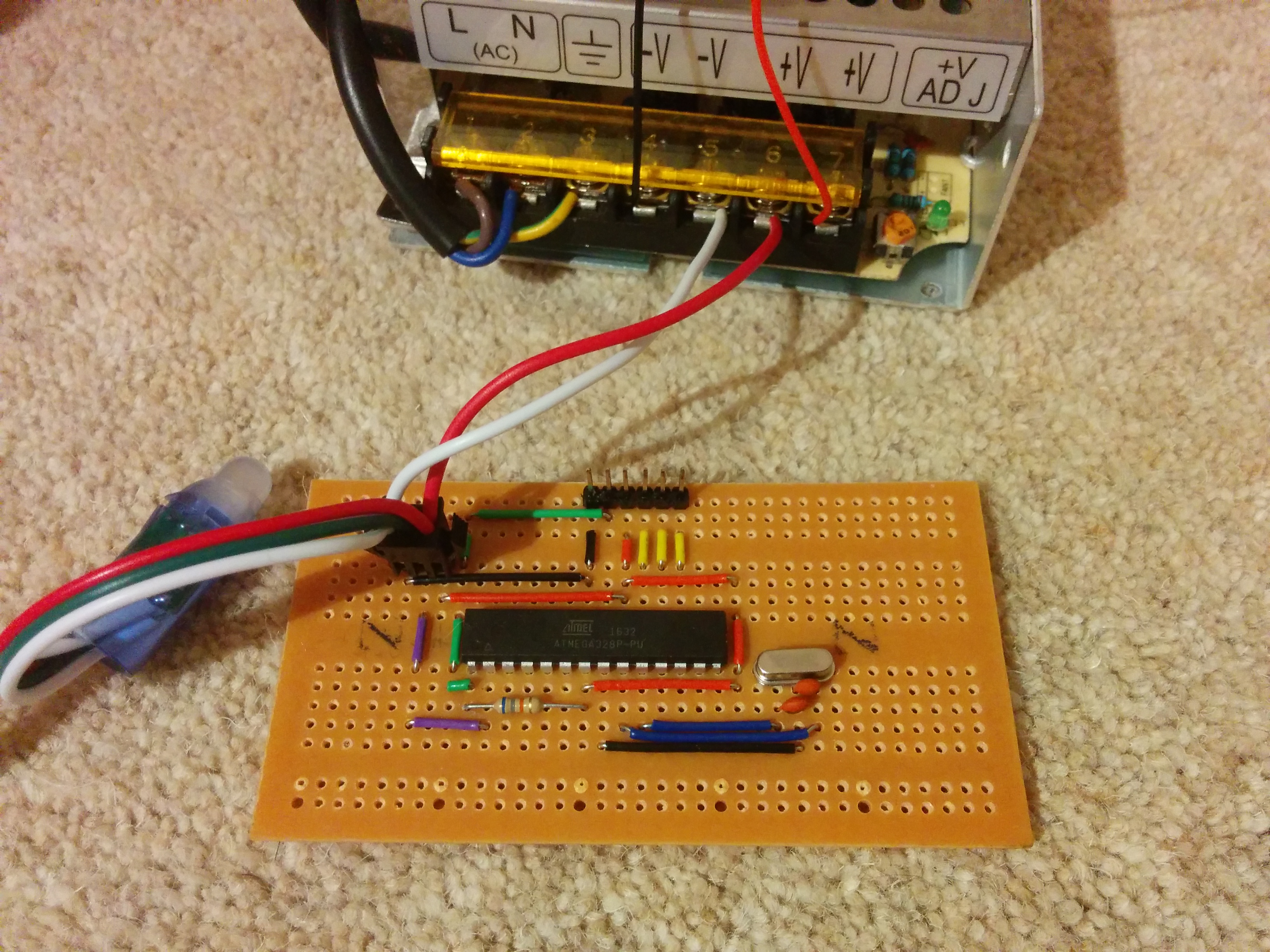
Ok ok, here is the whole program, and here’s the circuit board (before I added the mode-advancing button). Enjoy!