Programming an ATMega328P with a Raspberry Pi
The AVR series of microcontrollers are wonderful little devices with surprisingly many features built-in. The ATMega328P model sits at the heart of the famous Arduino Uno boards, and much of the useful functionality available on an Arduino actually comes directly from the microcontroller. The Arduino board adds handy things like USB support and compatibility with lots of add-on peripherals, but they’re expensive enough to make me think twice before hard-wiring them into something that just makes some lights flash on and off or something equally daft. The bare microcontrollers, on the other hand, are a fraction of the price, so I’m happy to use them fairly freely.
One of the features that the Arduino adds is a development environment that lets you program the microcontroller over the USB connection. “Programming” here means writing the compiled firmware into the on-chip flash memory so the microprocessor can execute it. Programming the microcontroller is obviously essential in any project, and this article is all about how I do that without needing the whole Arduino board around it.
Connecting a programmer
AVR microcontrollers support in-system programming (ISP): you can reset them
by pulling the !RESET pin low and then releasing it, and while the !RESET
pin is low you can talk to them over their Serial Peripheral Interface (SPI)
and give them instructions to overwrite the program stored in their Flash
memory. The SPI is three lines (called SCLK, MISO and MOSI), and this
means that you need at least 5 lines for ISP (3 lines for SPI, the !RESET
line and a common ground). Programmers normally add a power line so you don’t
need to provide power from elsewhere during programming, and the standard
connector for ISP is a 3x2 array of pins:
        MISO  ○ ○  Power
        SCLK  ○ ○  MOSI
      !RESET  ○ ○  GND
You can buy a USB-connected programmer for a few pounds (dollars, euros, etc.) that will attach your computer to this ISP connector and upload programs directly to the microcontroller. However, this connector is a royal pain if you want to build your circuit on stripboard because it means you have to break the tracks between holes, and also add quite a lot of wiring to join the connector’s pins up with the appropriate pins on the chip. Here’s what you’re aiming for on an ATMega328P:
    !RESET  1  ˘  ○
            ○     ○
            ○     ○
            ○     ○
            ○     ○
            ○     ○
     Power  ○     ○  GND
            ○     ○
            ○     ○  Power
            ○     ○  SCLK
            ○     ○  MISO
            ○     ○  MOSI
            ○     ○
            ○     ○
As you can see, five of the six lines are right next to each other, so it makes a bunch of sense to use this arrangement instead:
              ○  GND
              ○  !RESET
              ○  Power
              ○  SCLK
              ○  MISO
              ○  MOSI
This layout means that on stripboard you can line it up with the pins on the
chip and save a bunch of effort: just break the track from the !RESET line to
the pin on the chip and route that, and the power line, round to the other
side. Simples. I typically use a 6x1 pin
header for the physical connector.
Here is a photo of what it looks like in situ on a recent project:
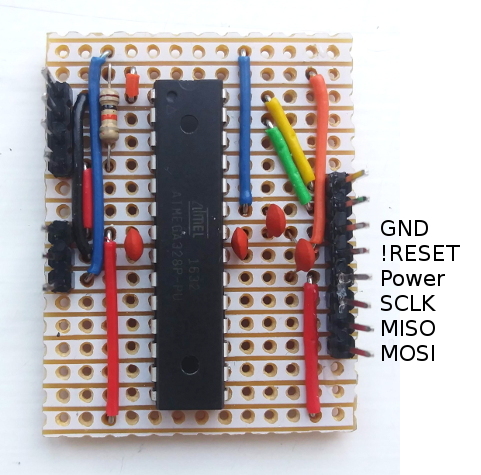
The ISP connector is the bottom 6 pins of the 8-pin header on the right, and the orange and red wires route things round to the far side of the chip.
El cheapo multiway connectors
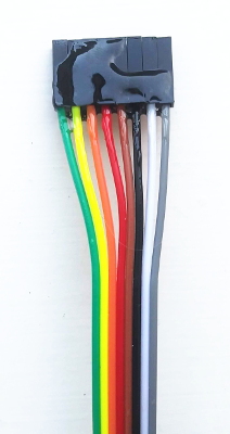
I normally connect to the pin header using a ribbon cable. I like the multicoloured ribbons that are sold fairly cheaply as “DuPont” wires on eBay. These are labelled with the same colour code as resistors, and I use these consecutive colours:
              ○  GND     = Black
              ○  !RESET  = Brown
              ○  Power   = Red
              ○  SCLK    = Orange
              ○  MISO    = Yellow
              ○  MOSI    = Green
It is a very happy coincidence that this lets GND be black and the power line
be red. I initially thought it’d be more elegant to have GND next to the
power line, but I was wrong.
The ribbon cables I use come with a separate connector for each pin. After a while it gets boring connecting the programmer pin-by-pin, so I normally add a blob of epoxy resin to stick them all together in the right order. Here’s the one that goes with the circuit pictured above, using a white and a grey wire for the extra two pins.
Raspberry Pi as programmer
As I mentioned above, you can get a USB-connected programmer quite cheaply. But for a little bit more money you can get a Raspberry Pi, a fully-fledged general-purpose computer running Linux that connects to your network, but which nonetheless lets you natively talk directly to hardware in ways that I fondly remember first doing with a BBC Micro back in the day.
In particular, Raspberry Pis have a SPI which can be used to program an AVR
microcontroller. The most convenient pins to use are here on the standard
40-pin connector, using GPIO pin 22 for the !RESET line:
             1 ○
             ○ ○
             ○ ○
             ○ ○
             ○ ○
             ○ ○
             ○ ○
    GPIO 22  ○ ○
      +3.3V  ○ ○
       MOSI  ○ ○
       MISO  ○ ○
       SCLK  ○ ○
        GND  ○ ○
             ○ ○
             ○ ○
             ○ ○
             ○ ○
             ○ ○
             ○ ○
             ○ ○
Note that the IO pins on a Pi run at 3.3V whereas Arduinos run at 5V. You will
apparently blow up your Pi if you expose it to a 5V signal on an IO pin, and
conversely 3.3V isn’t a big enough voltage to reliably register as a logically
HIGH signal in a 5V circuit, so they’re not trivially compatible. However,
AVR microcontrollers themselves run just fine at 3.3V, so you can connect them
together using 3.3V power as long as you’re sure there’s no 5V power anywhere
in the circuit.
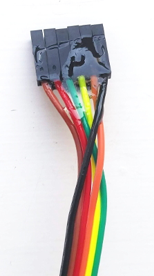
Of course these pins are in a different order from the ones on the microcontroller, but it’s great that they’re all adjacent: just like at the other end, it’s easy enough to make up a suitable connector by rearranging the wires and adding a blob of epoxy to keep them there:
Uploading firmware
That’s about it for the hardware side of things. Everything else needed to
program the microcontroller is software. The usual workflow is to write the
firmware for your project in some programming language (often C or C++) and
then to compile it down to the raw bytes that need to be written to the
microcontroller. The result of this process is a .hex file. If you are using
the Arduino development environment then you can compile your sketch to a
.hex file with the Sketch > Export Compiled Binary option, and find it with
Sketch > Show Sketch Folder.
Once you have a .hex file you can copy it into the on-chip flash memory on
the microcontroller using the AVR
Downloader/UploaDEr, a.k.a.
avrdude. The operating system of choice on a Pi is
Raspbian, a Debian
Linux derivative, which uses apt for package
management, so you can install avrdude with sudo apt-get install avrdude.
It supports a wide variety of different programmers, all configured in
/etc/avrdude.conf. The one we want to use is called linuxspi and by default
it uses GPIO pin 25 for the reset line, but I prefer to use pin 22 so this
needs adjusting:
#This programmer uses the built in linux SPI bus devices to program an
#attached AVR. A GPIO accessed through the sysfs GPIO interface needs to
#be specified for a reset pin since the linux SPI userspace functions do
#not allow for control over the slave select/chip select signal.
#
programmer
  id = "linuxspi";
  desc = "Use Linux SPI device in /dev/spidev*";
  type = "linuxspi";
  reset = 22;
  baudrate=200000;
;
You also need to enable the SPI interface by running sudo raspi-config and
selecting the appropriate options. Then you can write firmware.hex to an
ATMega328P with
sudo avrdude -P /dev/spidev0.0 -c linuxspi -p m328p -U flash:w:firmware.hex
Developing firmware on the Pi
You can write the firmware and compile it directly on the Raspberry Pi too,
using the AVR toolchain including the gcc-avr cross-compiler and the
avr-libc library.
sudo apt-get install gcc-avr avr-libc
A good first
program for a
microcontroller is one that makes an LED flash. Connect an LED and a 330Ω
current-limiting resistor to PB0 (the bottom-left pin) and save the following
program to a file called blink.c:
#include <avr/io.h>
#include <util/delay_basic.h>

int main (void)
{
    DDRB |= _BV(PORTB0);      // set pin 0 of port B as an output pin

    for (;;) {
        PORTB |= _BV(PORTB0);  // set pin 0 of port B high
        _delay_loop_2(62500);  // loop for 62500 iterations * 4 cycles / 1MHz clock ~= 250ms
        PORTB &= ~_BV(PORTB0); // set pin 0 of port B low
        _delay_loop_2(62500);  // loop for 62500 iterations * 4 cycles / 1MHz clock ~= 250ms
    }
}
Compile this to blink.o with
avr-gcc -Os -mmcu=atmega328p -I/usr/lib/avr/include -c blink.c
Link it to blink.elf with
avr-gcc -mmcu=atmega328p -o blink.elf blink.o
Create the firmware image blink.hex with
avr-objcopy -j .text -j .data -O ihex blink.elf blink.hex
Finally upload the firmware to your microprocessor with
sudo avrdude -P /dev/spidev0.0 -c linuxspi -p m328p -U flash:w:blink.hex
You can also dump the contents of blink.elf with
avr-objdump -h -S blink.elf > blink.dump
This makes it possible to look into how the compiler works. The basic AVR
instruction set is 8-bit (with a few 16-bit operations on certain registers)
and has no floating-point instructions, so it’s interesting to see how
operations on uint32_t and float variables are implemented. You can also
see how much extra code is needed to use everyday functions like snprintf()
or malloc() on a microcontroller.